
| 일 | 월 | 화 | 수 | 목 | 금 | 토 |
|---|---|---|---|---|---|---|
| 1 | 2 | 3 | 4 | |||
| 5 | 6 | 7 | 8 | 9 | 10 | 11 |
| 12 | 13 | 14 | 15 | 16 | 17 | 18 |
| 19 | 20 | 21 | 22 | 23 | 24 | 25 |
| 26 | 27 | 28 | 29 | 30 | 31 |
- ExoPlayer
- build with ai
- 독서
- Python
- kotlin collection
- ListAdapter
- FastAPI
- ktor api call
- map
- ChatGPT
- llm
- 스피너
- 시행착오
- android custom view
- DiffUtil.ItemCallback
- kotlin list
- getChangePayload
- android exoplayer
- list map
- video caching
- AWS EC2
- exoplayer cache
- 안드로이드
- ListAdapter DiffUtil
- Zsh
- 유튜브
- android ktor
- doc2vec
- ktor client
- android
- Today
- Total
버튼 수집상
[안드로이드] 모서리가 둥근 뷰파인더 만들기 rounded square transparent mask for zxing barcode reader UI 본문
[안드로이드] 모서리가 둥근 뷰파인더 만들기 rounded square transparent mask for zxing barcode reader UI
cocokaribou 2023. 12. 14. 15:08배경
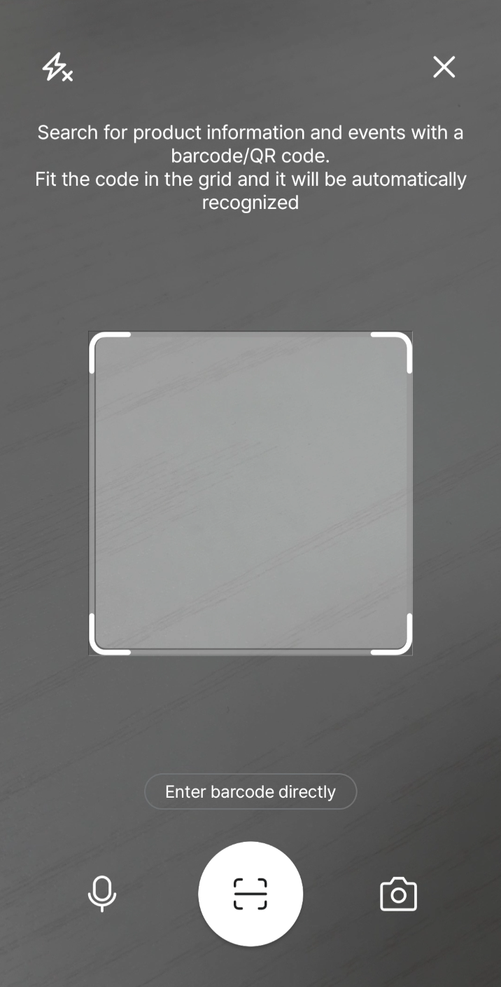
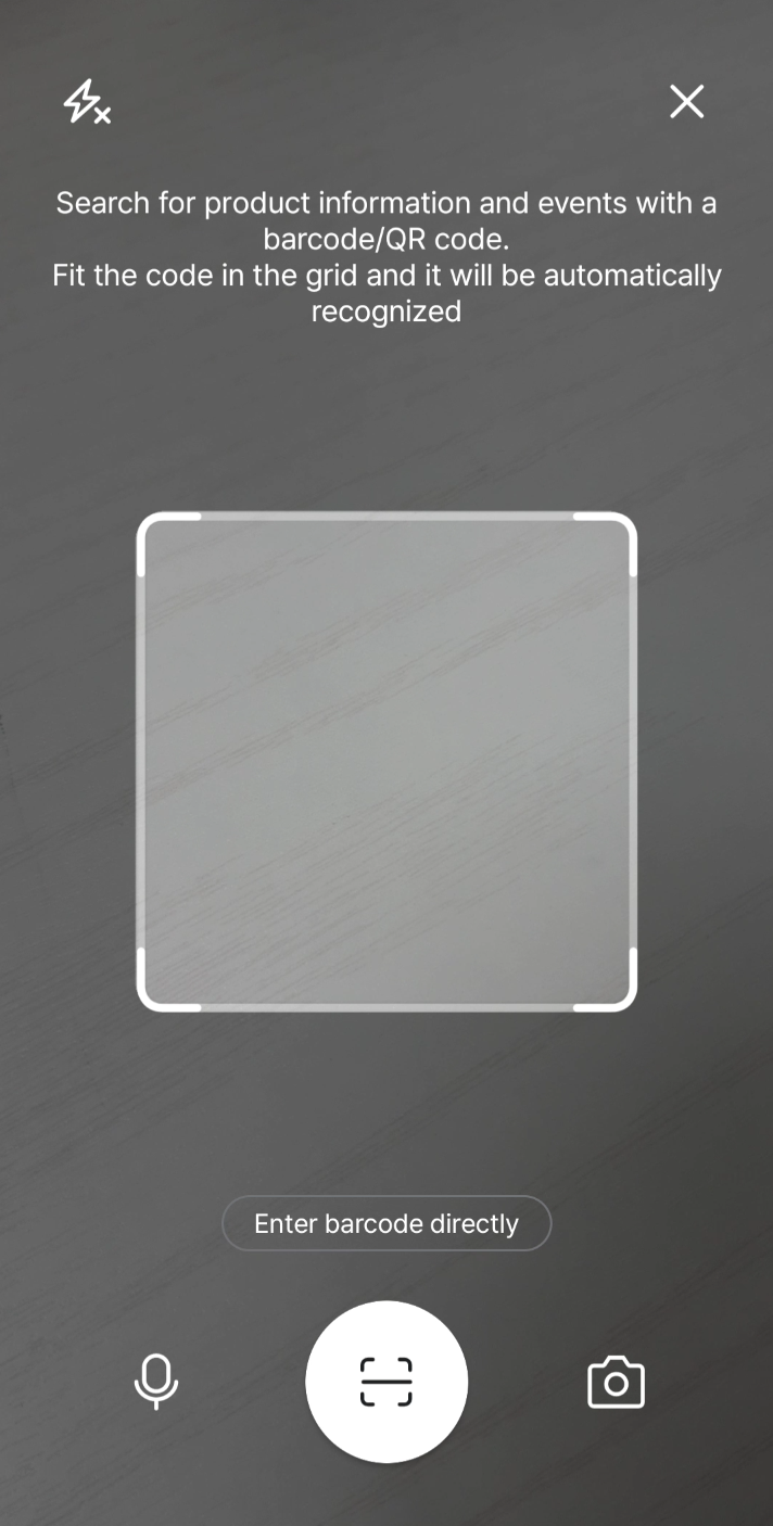
바코드리더기 가이드 뷰가 각진 사각형에서 둥글게 바뀌었다.
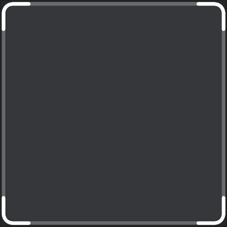
그런데 배경 필터에 (뷰파인더 영역) 모서리가 하얗게 남았다.
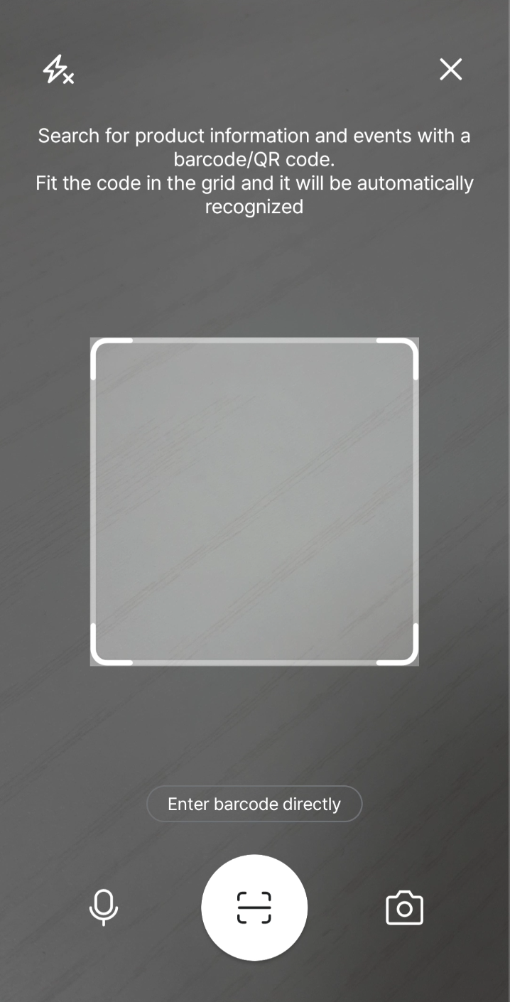
저 하얀 모서리를 둥글게 메꿔보겠다.
기존의 DecroatedBarcodeView 화면 (view_barcode_scanner.xml)
<merge xmlns:android="http://schemas.android.com/apk/res/android"
    xmlns:app="http://schemas.android.com/apk/res-auto">
    <RelativeLayout
        android:layout_width="match_parent"
        android:layout_height="match_parent">

        <com.journeyapps.barcodescanner.BarcodeView
            android:id="@+id/zxing_barcode_surface"
            android:layout_width="match_parent"
            android:layout_height="match_parent"
            app:zxing_framing_rect_width="247dp"
            app:zxing_framing_rect_height="247dp"/>

        <m.sample.com.ui.custom.ViewFinderViewEx
            android:id="@+id/zxing_viewfinder_view"
            android:layout_width="match_parent"
            android:layout_height="match_parent"/>

    </RelativeLayout>
</merge>
바코드 리더기는 zxing 라이브러리를 쓰고 있다.
ViewFinderViewEx는 zxing에서 제공하는 ViewfinderView를 상속해서 만든 커스텀뷰이다.
기존의 커스텀뷰 (ViewFinderViewEx.kt)
// zxing 라이브러리의 뷰파인더 UI 상속해서 커스텀
class ViewFinderViewEx @JvmOverloads constructor(
    context: Context, attrs: AttributeSet? = null
) : ViewfinderView(context, attrs) {

    override fun onDraw(canvas: Canvas?) {
        refreshSizes()
        // framingRect는 BarcodeView에서 받아옴
        if (framingRect == null || previewFramingRect == null) return

        // 반투명한 검은색 적용
        paint.color = maskColor
        canvas?.let {
            it.drawRect(0f, 0f, width.toFloat(), framingRect.top.toFloat(), paint)
            it.drawRect(0f, framingRect.top.toFloat(), framingRect.left.toFloat(), (framingRect.bottom + 1).toFloat(), paint)
            it.drawRect((framingRect.right + 1).toFloat(), framingRect.top.toFloat(), width.toFloat(), (framingRect.bottom + 1).toFloat(), paint)
            it.drawRect(0f, (framingRect.bottom + 1).toFloat(), width.toFloat(), height.toFloat(), paint)
        }

        // resultBitmap은 가이드뷰UI를 받아옴
        if (resultBitmap != null) {
            paint.alpha = 0xFF
            canvas?.drawBitmap(resultBitmap, null, framingRect, paint)
        }
    }
}
가운데 framingRect를 둘러싼 반투명 배경을 네 조각으로 나눠서 그리는 것을 알 수 있다.
해결법1
가이드뷰 벡터 이미지의 모서리에 반투명한 검은색을 채워넣는다.
원리는 간단하게 아래와 같다.
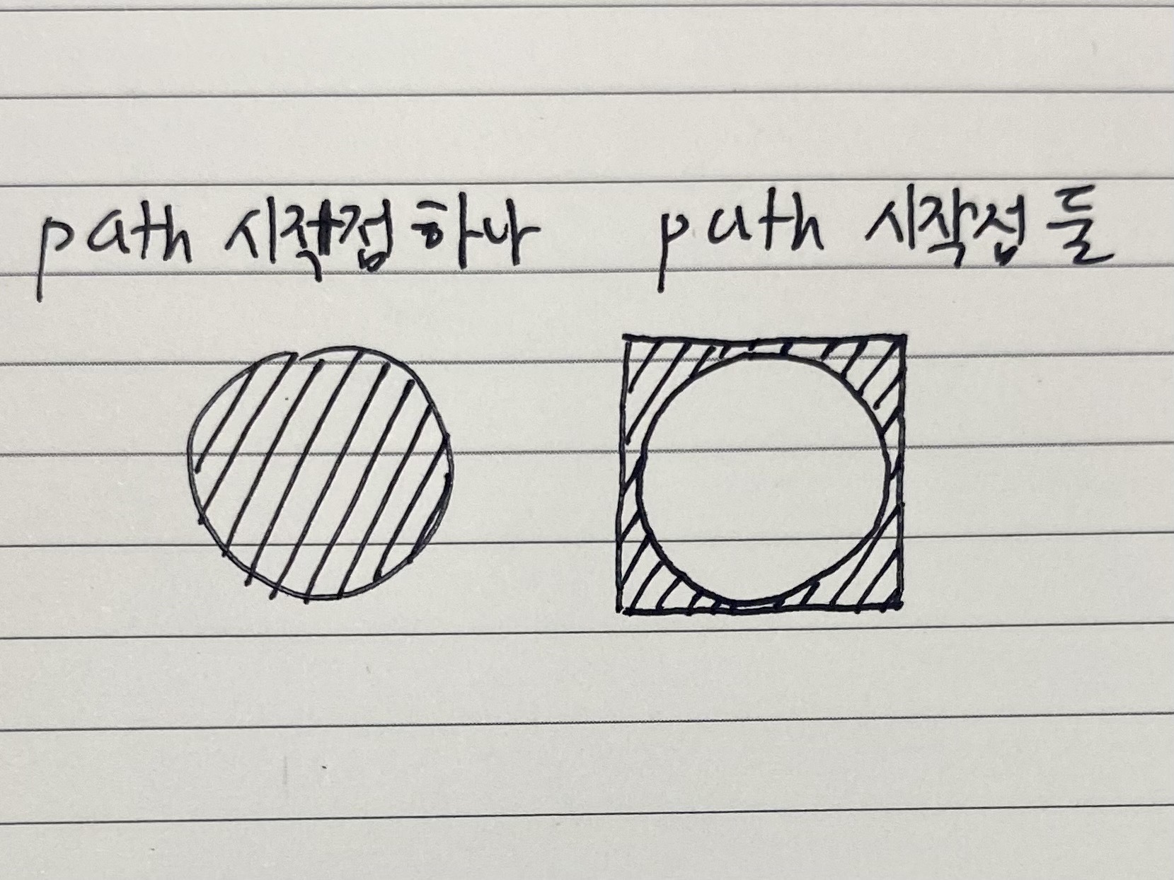
현재 그려져있는 패스에 전체영역을 꽉 채우는(뷰포트) 사각형 패스를 추가한다.
그러면 두 패스 사이의 교집합이 영역으로 잡히면서 모서리가 채워진다.
가이드뷰 벡터 이미지 (bg_barcode.xml)
<?xml version="1.0" encoding="utf-8"?>
<vector xmlns:android="http://schemas.android.com/apk/res/android"
    android:width="250dp"
    android:height="249dp"
    android:viewportWidth="250"
    android:viewportHeight="249">
    <path
        android:fillAlpha="0.4"
        android:fillColor="#000000"
        android:pathData="M0,0h250v250h-250v-250 M237.82,4.76H13.82C9.4,4.76 5.82,8.35 5.82,12.76V235.76C5.82,240.18 9.4,243.76 13.82,243.76H237.82C242.24,243.76 245.82,240.18 245.82,235.76V12.76C245.82,8.35 242.24,4.76 237.82,4.76Z" />
    <!-- 아래 패스들 생략 -->
</vector>
둥근 사각형을 잡는 패스를 하나 가져온 뒤, 패스 M0,0h250v250h-250v-250 를 추가한다
점(0,0)에서 출발해서 횡으로 250, 종으로 250, 횡으로 -250, 종으로 -250 이동하여 전체 뷰포트 영역을 잡는다.
뷰포트 영역을 패스로 추가해도 도형 바깥 영역이 생기지 않을 때.
그럴땐 4개의 모서리 바깥 영역을 잡는 패스를 만들어줘야 한다.
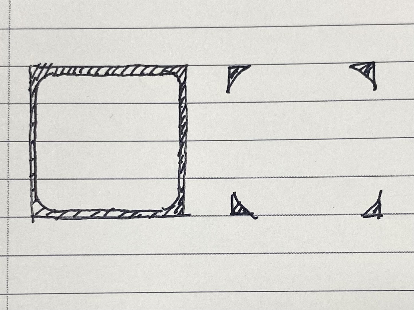
vector drawble path로 곡선을 그리는 명령어는 아래와 같다.
A: 원호를 이용한다
Q: 2차 베지어 곡선
C: 3차 베지어 곡선
예시로 viewport 250*250, radius 15의 둥근 사각형의 바깥 모서리 영역을 Q와 C를 이용해서 그려보겠다.
C: 3차 베지어 곡선
<?xml version="1.0" encoding="utf-8"?>
<vector xmlns:android="http://schemas.android.com/apk/res/android"
android:width="250dp"
android:height="250dp"
android:viewportWidth="250"
android:viewportHeight="250">
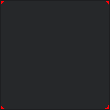
<path
android:fillColor="#ff0000"
android:pathData="M15,0C7.5,0,0,7.5,0,15v-15"/>
<path
android:fillColor="#ff0000"
android:pathData="M235,0C242.5,0,250,7.5,250,15v-15"/>
<path
android:fillColor="#ff0000"
android:pathData="M0,235C0,242.5,7.5,250,15,250h-15"/>
<path
android:fillColor="#ff0000"
android:pathData="M235,250C242.5,250,250,242.5,250,235v15"/>
</vector>3차 곡선이므로 좌표로 된 매개변수가 3개이다.
M[곡선 시작점 좌표]C[제어점1 좌표],[제어점2 좌표],[곡선 도착점 좌표]
시작점과 도착점을 먼저 쓰고 그 사이에 제어점 두 개를 쓰면 편하다.
헷갈릴 땐 이 사이트에서 직접 보는 것을 추천한다.
https://codepen.io/thebabydino/full/EKLNvZ
how stuff works: cubic Bézier curve with SVG
Aims to visually explain what looks like markup vomit at first sight. Hover numbers in code/ points on graph. Drag points on graph....
codepen.io
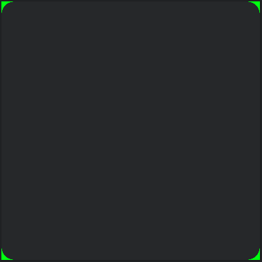
Q: 2차 베지어 곡선
<?xml version="1.0" encoding="utf-8"?>
<vector xmlns:android="http://schemas.android.com/apk/res/android"
    android:width="250dp"
    android:height="250dp"
    android:viewportWidth="250"
    android:viewportHeight="250">

    <path
        android:fillColor="#00ff00"
        android:pathData="M15,0Q0,0,0,15v-15"/>

    <path
        android:fillColor="#00ff00"
        android:pathData="M235,0Q250,0,250,15v-15"/>

    <path
        android:fillColor="#00ff00"
        android:pathData="M0,235Q0,250,15,250h-15"/>

    <path
        android:fillColor="#00ff00"
        android:pathData="M235,250Q250,250,250,235v15"/>
</vector>
C 명령어보다 매개변수가 하나 적다.
M[곡선 시작점 좌표]Q[제어점 좌표],[곡선 도착점 좌표]
좌표 그리기는 아래 링크를 참고했다.
SVG 패스 도형 그리기 - Graphics ARIA Guidebook
d="M248.761,92c0,9.801-7.93,17.731-17.71,17.731c-0.319,0-0.617,0-0.935-0.021c-10.035,37.291-51.174,65.206-100.414,65.206 c-49.261,0-90.443-27.979-100.435-65.334c-0.765,0.106-1.531,0.149-2.317,0.149c-9.78,0-17.71-7.93-17.71-17.731 c0-9.78,7.93-17.71,17.71-1
a11y.gitbook.io
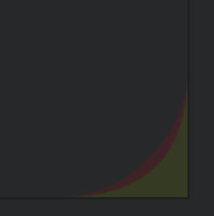
해결법1의 문제점1
직사각형으로 잡혀있는 뷰포트에서 네 모서리만 둥글게 채워도 UI가 자연스럽지 않다.
반투명한 색이라 겹치는 부분은 진해지기도 하면서 사각형이 비쳐보인다.
해결법1의 문제점2
안쪽 모서리의 곡률을 꼭 맞춰서 바깥 모서리를 그리지 않으면 UI가 어색하다.
UI 툴 없이 패스만으로 곡률을 맞추기가 어려웠다.
해결법2
뷰파인더의 투명 영역을 직사각형에서 둥근 사각형으로 수정한다.
// zxing 라이브러리의 뷰파인더 UI 상속해서 커스텀
class ViewFinderViewEx @JvmOverloads constructor(
    context: Context, attrs: AttributeSet? = null,
) : ViewfinderView(context, attrs) {
    private val radius = 15.toPx.toFloat() // 값이 높을수록 둥긂

    // onDraw 밖에서 미리 객체만 생성
    private val backgroundRect = Rect() // 반투명한 전체 영역
    private val roundRect = RectF() // 투명한 바코드 인식 영역

    // ⚠️투명 Paint
    private val transparentPaint = Paint().apply {
        setLayerType(LAYER_TYPE_SOFTWARE, null)
        xfermode = PorterDuffXfermode(PorterDuff.Mode.CLEAR)
    }

    override fun onDraw(canvas: Canvas?) {
        refreshSizes()
        if (framingRect == null || previewFramingRect == null) return

        // framingRect는 상속받은 값
        roundRect.apply {
            left = framingRect.left.toFloat()
            top = framingRect.top.toFloat()
            right = framingRect.right.toFloat()
            bottom = framingRect.bottom.toFloat()
        }

        backgroundRect.apply {
            left = 0
            top = 0
            right = width
            bottom = height
        }

        paint.apply {
            color = maskColor // 상속받은 값
            alpha = 0x66
        }

        val guideViewVector =
            VectorDrawableCompat.create(context.resources, R.drawable.bg_barcode, null)?.apply {
                setBounds(roundRect.left.toInt(), roundRect.top.toInt(), roundRect.right.toInt(), roundRect.bottom.toInt())
            }

        canvas?.let {
            // 반투명 배경
            it.drawRect(backgroundRect, paint)

            // radius적용된 투명 프레임 (바코드 인식)
            it.drawRoundRect(roundRect, radius, radius, transparentPaint)

            // 가이드뷰
            guideViewVector?.draw(it)
        }
    }
}
View의 canvas 객체에는 다양한 draw 함수가 지원된다.
그 중 drawRoundRect()는 RectF 객체를 받아와서 radius를 적용시킨 뒤 화면에 그려준다.
위처럼 수정해주면 모서리 바깥 영역이 어색하지 않게 꽉 채워지는 것을 볼 수 있다.
'TIL - 안드로이드' 카테고리의 다른 글
| [안드로이드] 웹크롬클라이언트로 웹뷰 새 창 처리하기 WebChromeClient onCreateWindow (0) | 2024.04.01 |
|---|---|
| [안드로이드] 검색어 자동완성 커스텀 뷰 만들기 Custom Auto Complete View (0) | 2024.03.28 |
| [안드로이드] Retrofit 대신 Ktor로 Api 호출해보기 - 2 (0) | 2023.12.11 |
| [안드로이드] Retrofit 대신 Ktor로 Api 호출해보기 - 1 (0) | 2023.12.11 |
| [안드로이드] TextView 원하는 글자만 남기고 말줄임표 보여주기 Custom Ellipsis (1) | 2023.12.07 |

